Welcome back to The Whys of Bike Tech!
So far we have looked at frame materials and how the properties work with the design to influence the stiffness characteristics of the frame. And we’ve considered the parts of the bicycle that can have a meaningful impact on rider comfort. These are two important factors affecting how the bike feels and handles, but they don’t help us much unless the geometry is designed appropriately. Certainly, this is an enormous topic, and I’ll start by considering the basics of bicycle geometry as related to the rider’s fit.
As a frame builder, I first ask clients about their bike fit. Do they have a bike now where they are completely comfortable? Are they looking to change anything to improve comfort or efficiency or power? As Matt Wikstrom suggested in his guide to buying a bespoke bicycle, I also recommend seeking a reputable fitter with a fully adjustable fit bike, so that the riding position can be adjusted without constraints.
I don’t know who originally coined the phrase, but we have a bicycle that is somewhat adjustable and a body that is somewhat adaptable. This means there isn’t necessarily a single right answer for bike fit, but typically a range of positions that the body will be able to adapt to. Working with a fitter who can give suggestions whilst listening to what the rider is experiencing can help improve the riding position. Ideally, any changes made are matched on the rider’s bike so they can test it on the road for several weeks to allow for any adaptation and ensure the changes were positive.
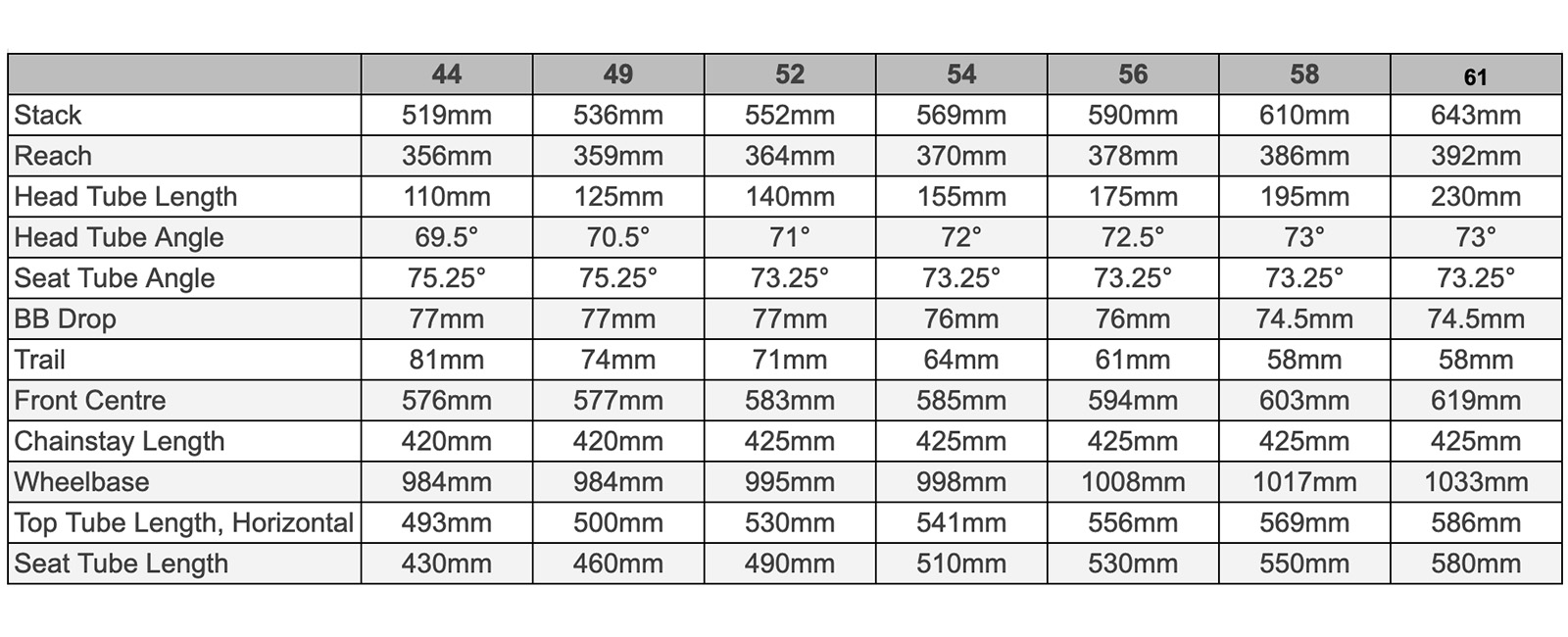
With the fit confirmed, the contact points of the saddle and handlebar can be located accurately relative to the bottom bracket. For a custom bike, the builder can use these fixed points to create a bespoke design. For a stock or mass-market bike, careful reading of geometry charts can hopefully find a bike that can use the adjustments available to meet the required fit.
Basic fit numbers

Traditionally, when bikes all had horizontal top tubes, frame sizes were defined by the length of the seat tube (with road bikes in centimeters and mountain bikes in inches; good old bike industry …). A “square” frame was most common, where the top tube length would equal the seat tube. Frame sizes might be in two-centimetre increments, and so a rider would choose a frame size that, when paired with the correct-length stem, would put the handlebar in the right place for their fit.
Modern bikes are more commonly using some variation of small, medium, large for sizing, an often-reduced range which means that riders need to carefully study the geometry charts to see which model/size might best match their fit dimensions. For those coming from a more traditional frame, the effective top tube measurement is useful here – this is a horizontal measurement from the head tube to the seat post which would give that familiar dimension (ie. a rider might generally ride a 56 cm). However, this measurement doesn’t consider the frame angles or the fork/head tube length. These variables can significantly impact what that effective top tube dimension means for fit.
The current industry solution is to have independent dimensions for knowing where the front of the frame is and where the saddle is, using the center of the bottom bracket as the reference point. The terms adopted for the front of the frame are stack and reach.
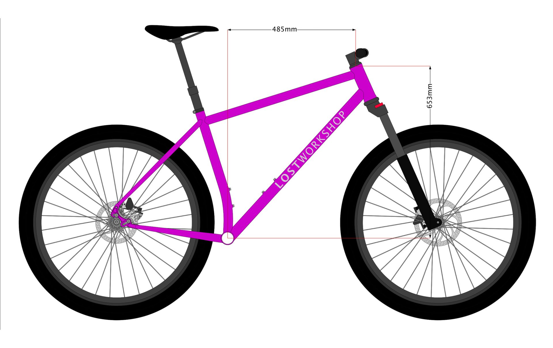
Stack is the vertical distance from the bottom bracket center to the top of the headtube/headset, while reach is the horizontal distance between the two same points. This is helpful in providing a reasonable way to compare the frame sizes across brands.
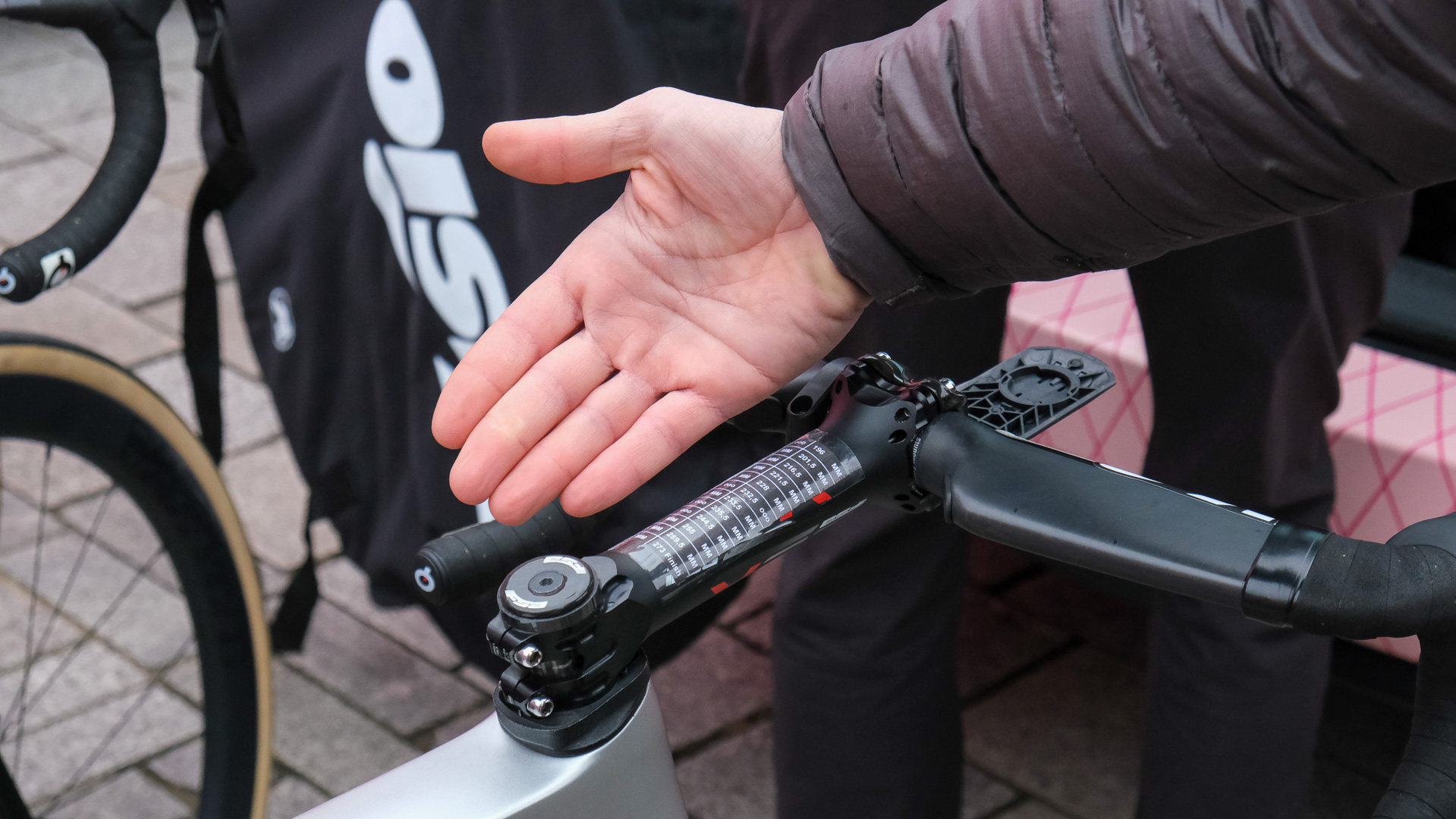
Adding a stem to this will then position the handlebar – traditionally, the stem has options for length and angle, plus the ability to install spacers underneath it, all of which allow for a considerable range of adjustment. Figuring out exactly where the bar will ultimately land can be challenging without drawing the geometry. Before the advent of integrated everything, most bike shops would have a box of stems that could help figure out what the rider needed. Today, there is often little to no adjustment, and changing a one-piece bar/stem to adjust the fit can be an expensive and complicated proposition.
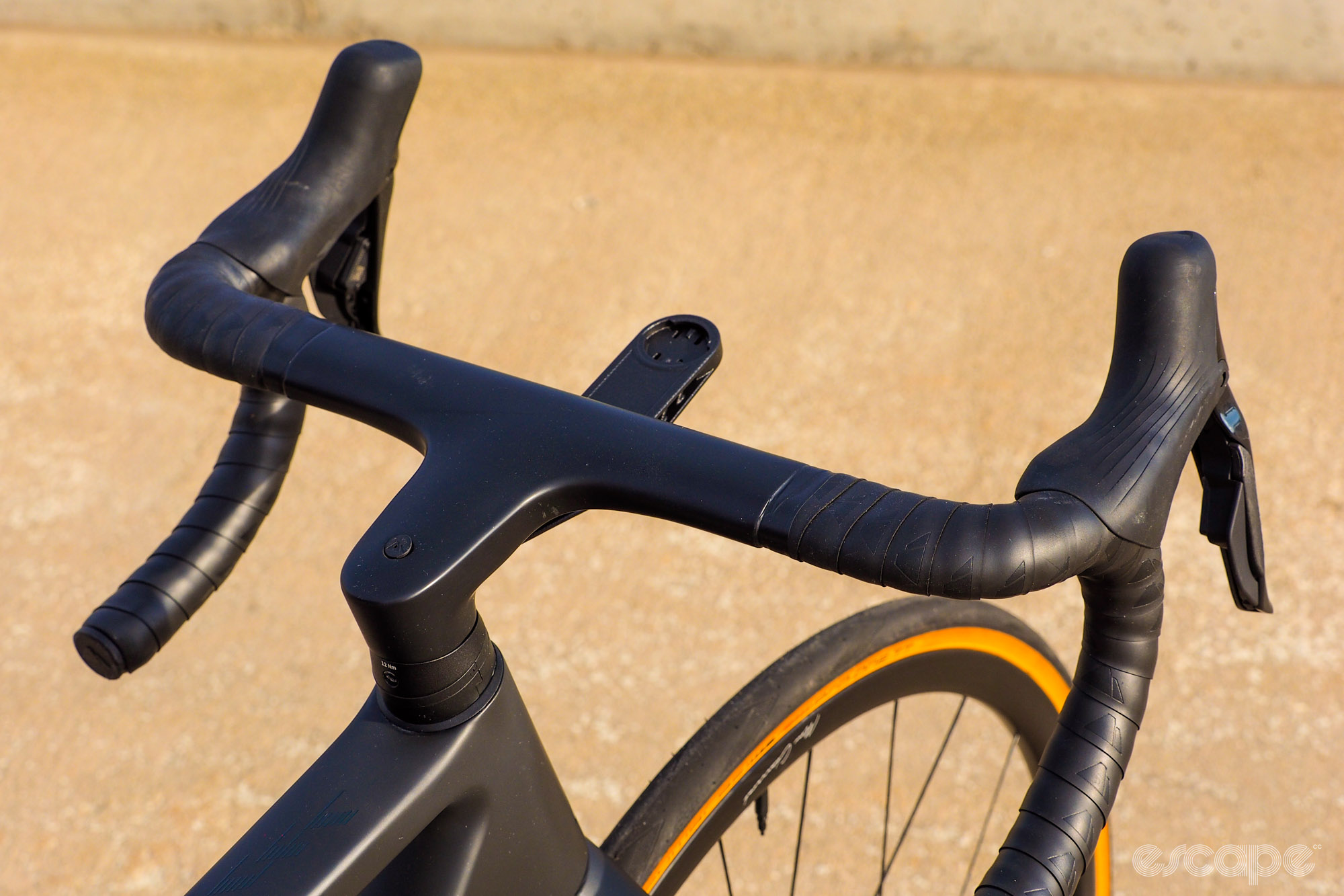
For riders that might need a higher handlebar, be aware that most carbon forks have limitations on the number of spacers that can safely be used under the stem. This is due to the leverage of that unsupported length of carbon steerer tube above the upper headset bearing. It may not be as pleasing to the eye, but it is better to use a stem with an upward angle to position the bars correctly.
The length of the stem is also an important part of the steering geometry. I think of this as the ‘tiller’ effect, with a longer stem requiring greater hand movement for the same rotation of the front wheel. So whilst using a super-short stem to achieve the required fit might seem fine, it may lead to overly quick handling if the frame wasn’t designed with that in mind.
For positioning the saddle, the setback (considered as the horizontal distance of the nose of the saddle behind the center of the bottom bracket) needs to be correct at the required saddle height. This is an important aspect of the rider’s position, because the biomechanics of pedaling change as the saddle is moved relative to the bottom bracket. For this reason, the available fore-aft adjustment of the saddle rails should only be used to position the saddle correctly, and not to compensate for a bike where the reach to the bars is too short or long.
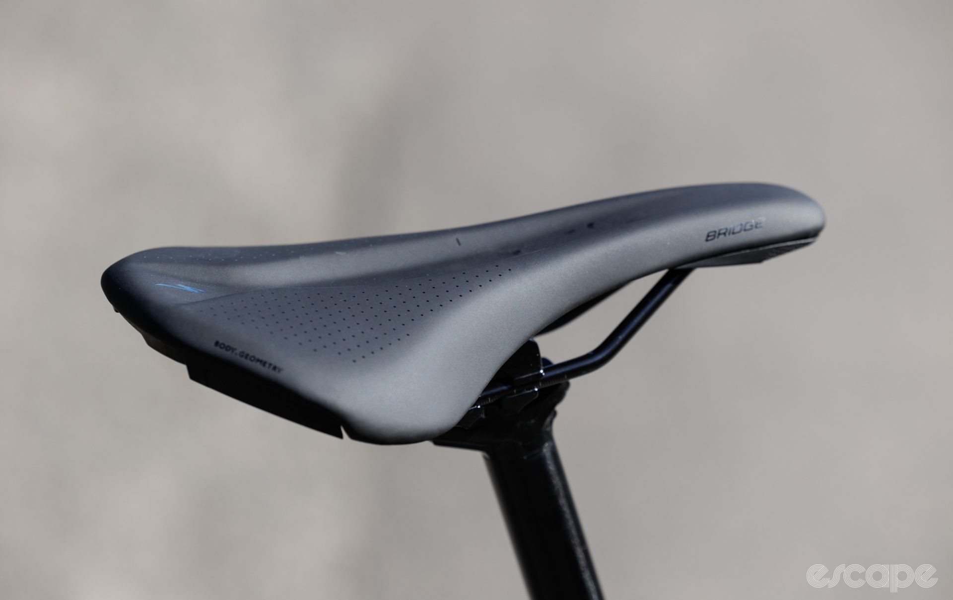
The saddle setback is influenced by the seat tube angle; a slacker angle will see the saddle move back more as it is raised. Evaluating this can be a bit more complicated with bikes with non-straight or offset seat tubes, and it may be necessary to measure the bike to see if it will work. Using a seat post with more or less setback can help, but this isn’t always an option for those frames with a proprietary system.
Pedal to ground height and toe overlap
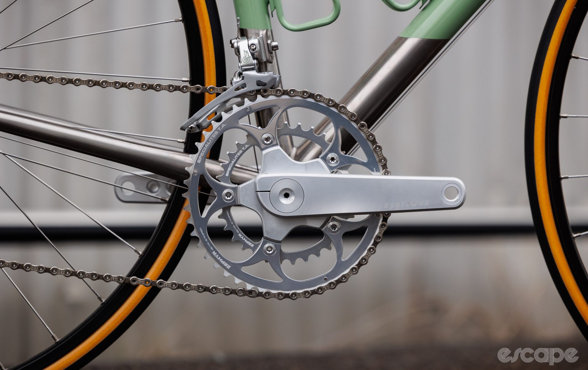
An often overlooked aspect of fit is the pedal-to-ground height. Four factors influence this: crank length, crank Q-factor, overall wheel diameter, and the bottom bracket drop.
Normally quoted on a geometry chart, the bottom bracket drop is the distance that the centre of the bottom bracket is below the wheel centres (hub axles). Increasing the wheel/tire size from the stock option will raise the bottom bracket (but not drop), and raise the pedals from the ground. Meanwhile, decreasing the crank length will have a similar impact on the pedal height and handling even though the BB drop itself does not change.
Q-factor is the distance between the outer faces of the cranks, basically the pedal or stance width. As this gets wider, it makes the pedal closer to the ground when the bike is lent over in a turn. The style of pedal is also a consideration here – a flat (aka platform) pedal will likely be closer to the ground when leaning than a smaller clipless pedal; to a lesser degree, a mountain clipless pedal will be closer to the ground than a road version.
The pedal-ground height didn’t used to be too much of a consideration except in narrow use cases like criteriums and cyclocross. In the past, road tires were all the same (narrow!) size, and cranks had approximately the same Q-factor and only a five mm variation in length. Now though, with “all-road” bikes allowing a wide range of tire sizes to be fitted (or even wheel sizes with the 650B option), and cranks becoming more commonly available with a greater number of length options, it is a bit surprising that it isn’t mentioned more often – though possible that’s because the issues come at the extremes.
If we have a frame with a larger bottom bracket drop (perhaps designed around 40mm tires and 170mm cranks), that is then equipped with 28mm tires and 175mm cranks – suddenly the pedal is 11mm closer to the ground. Add in a wider crank and larger pedals, and the ability to pedal through a corner will likely be hindered. Striking a pedal in a corner is not very fun (or to be more specific, crashing at speed as a result of such an event isn’t fun)!
At the other end, bumping up the tire size and shortening the crank puts the rider that much higher on the bike – better for pedaling through corners and rock clearance, but perhaps feels a bit less stable and harder to get a toe to the ground when stopped in the saddle.
Another consideration which includes crank length and tire size is whether there will be overlap between the toe and the front wheel when the wheel is turned. Whilst not a terrible trait, and one that the rider can learn to compensate for, it can lead to falls at slow speed. The front center of the bike (the distance from the center of the bottom bracket to the front axle) is the relevant geometry number here. Longer cranks, larger shoes and larger tires will make overlap more likely (as will a full coverage front mudguard).
Weight distribution
The final piece to consider here with how the basics of geometry relate to the rider’s position is with weight distribution. There is no exact science about this, but as a designer, I look at the safety consideration of descending at speed. With my best estimate of how the rider sits on the bike, my goal is to have the weight distribution aimed at 55% on the front wheel and 45% on the rear when going downhill.
This may seem a little counterintuitive at first glance, but using a basic model and making my best estimate of where the combined rider and bike center of mass falls, a weight distribution of 55% rear wheel and 45% front wheel is almost reversed (with more weight on the front wheel), on a moderate, eight-percent downhill grade. This approach means that if there is a loss of traction in a turn, the rear wheel should break first, which allows a much greater chance of recovery than when the front wheel slides.
How the rider sits on the bike has the biggest impact on the weight distribution. For a rider who sits further behind the bottom bracket and perhaps more upright, the rear wheel will carry a greater proportion of the weight. So to achieve that descending safety goal, a frame with longer chainstays (this moves the rear wheel further back, helping to distribute some of the weight to the front wheel) would be helpful. Similarly, a rider sitting forward and in an aggressive position may carry more weight at the front wheel. For this rider, there would be a benefit in very short chainstays to help share that weight more with the rear wheel.
Both situations are also influenced by the front centre measurement – how far forward the front wheel is – and the stem length (how far in front of the front wheel the rider weight is applied). This weight distribution piece is worth considering when a rider is in between frame sizes. For example, the correct fit might be achieved with a medium frame and a 120mm stem, or a large frame and a 90mm stem.
Assuming the same headtube angle and fork offset, the larger (greater reach dimension) frame will also have a greater front-centre measurement. For the example positions given, the upright rider would likely have better weight distribution on the smaller frame with the longer stem, and the aggressive rider may be better served with the larger frame and shorter stem.
Obviously, this is a tricky and well-nuanced subject. Next time I will expand this topic to look at what the geometry numbers mean for how the bike handles, and where some of the compromises are when trying to get the fit just right and have the bike perform as required.
The Whys of Bike Tech is a column from American-based custom frame maker Rob English of English Cycles. This column looks to mix opinions from hands-on experience with a mechanical engineering background to break down commonly misunderstood subjects and myths in the world of cycling tech.
Lead photo provided by custom frame builder, Albatross Bikes.
What did you think of this story?
